A grain silo explosion is essentially a chain reaction: suspended dust ignites, the resulting flame front compresses unburned dust ahead of it, and within 50 milliseconds the pressure wave can rupture an unprotected silo wall. Combustible dust protection systems work by attacking this chain at three points — venting the pressure before structural failure, suppressing the flame chemically before it propagates, and isolating connected ductwork so the explosion cannot jump to the next vessel. Get any one of those wrong and you don't have a protection system, you have a delay timer.
What Actually Happens Inside the First 100 Milliseconds
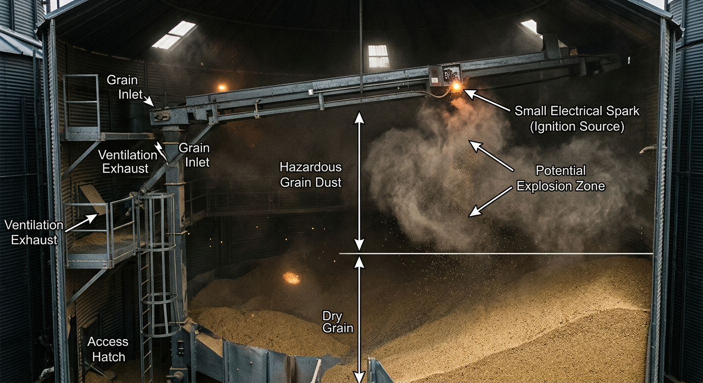
Most people picture a grain silo explosion as one big bang. It's not. It's a sequence — and understanding the sequence is the entire reason protection hardware exists.
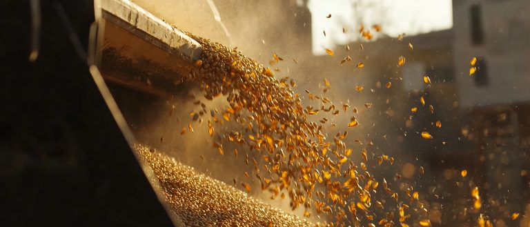
It starts with a primary ignition: a hot bearing, a tramp metal spark, an overheated motor, or static discharge in dry winter air. That ignition only needs about 30 mJ of energy to set off a grain dust cloud at the right concentration (typically 50–100 g/m³). Within the first 10 ms, a flame kernel forms. By 30 ms, the flame front is moving at 10–30 m/s and pressure inside the silo is rising past 0.2 bar. By 50–80 ms, an unprotected silo built for static loading sees its head plate or wall fail.
But here's the part operators forget: the primary explosion almost never causes the worst damage. The pressure wave travels through dust collection ducts, conveyors, and bucket elevators, kicking settled dust off ledges and beams elsewhere in the facility. That airborne dust meets the trailing flame front and you get a secondary explosion — often ten times more destructive than the first. The 2008 Imperial Sugar refinery disaster in Georgia, which killed 14 workers, was a textbook secondary-explosion event.
Why Grain Dust Is Particularly Nasty
Not all combustible dust behaves the same way. Grain dust — wheat, corn, soy, barley — sits in a sweet spot of danger that makes it harder to handle than coal or wood.
- Low minimum ignition energy: 30–60 mJ. A static spark from a worker's coat can do it.
- Kst value of 100–150 bar·m/s: classified as a Class St 1 dust, which sounds mild but means a vented silo still needs to handle several bar of overpressure.
- Particle size below 75 microns: the fine fraction generated by handling and transport stays airborne for minutes.
- Moisture sensitivity: below 13% moisture content, ignitability climbs sharply. Winter grain in a heated facility is the worst case.
For instance, a Midwest soybean processor we've worked alongside found that simply rerouting their pneumatic conveying line — which was generating fines through impact attrition at every elbow — dropped their dust-loading inside the receiving silo by 40%. No new hardware. Just better routing. That's the kind of detail that doesn't show up in a generic safety audit.
Explosion Venting: The First Line of Defense
Explosion vents are the unsung heroes of dust safety. They're passive, they're cheap, and they work in milliseconds without any electronics.
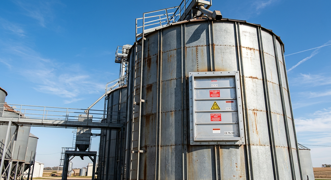
A vent panel is a calibrated weak spot in the silo wall — usually a stainless steel rupture disc with a scored pattern designed to fail at a precise pressure, typically 0.1 bar (10 kPa). When the internal pressure rises during an incipient explosion, the panel opens before the silo's structural limit is reached, releasing the flame ball and pressure wave to a safe outdoor area.
Sizing Is Where Most Designs Go Wrong
Vent area calculations follow EN 14491 or NFPA 68. The required area scales with vessel volume, Kst, and the reduced explosion pressure (Pred) the silo can survive. A 200 m³ steel silo handling wheat dust typically needs 4–6 m² of vent area. Undersized by even 20% and Pred climbs above the silo's design strength. We've seen retrofits where the vent area was technically present but oriented toward an occupied loading bay — a fatal design choice. Vents must discharge to a clear zone, generally a 10–15 m hazard radius.
When Outdoor Venting Isn't an Option
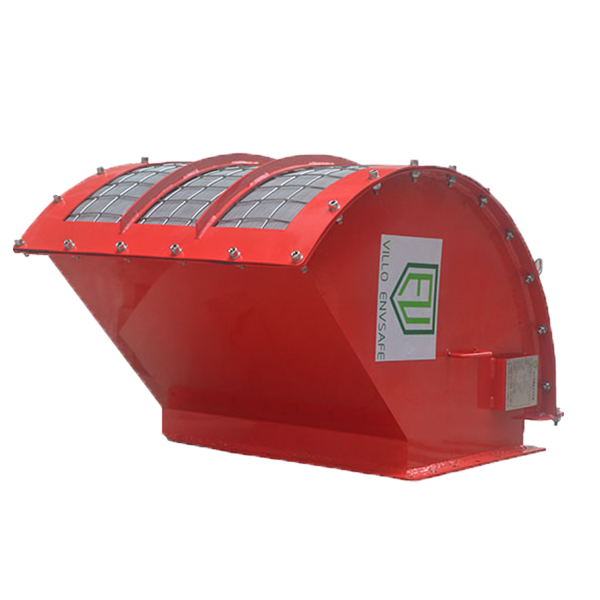
Indoor silos or those near occupied buildings can use flameless venting devices, which incorporate a stainless steel mesh quench element. The flame is cooled below the auto-ignition temperature of grain dust as it passes through the mesh, so only cool gas exits. Pressure relief without the fireball.
Explosion Isolation: Stopping the Fireball at the Duct
Venting alone protects the silo. It does nothing for the equipment connected to it. That's where isolation comes in — and it's where most older facilities are quietly non-compliant.
A grain silo is rarely a standalone vessel. It's connected to bucket elevators, drag conveyors, dust collectors, and pneumatic transport lines. An explosion in the silo will propagate through any of those at flame speeds approaching 100 m/s. Without isolation, your downstream baghouse becomes the next bomb.
Two main isolation strategies:
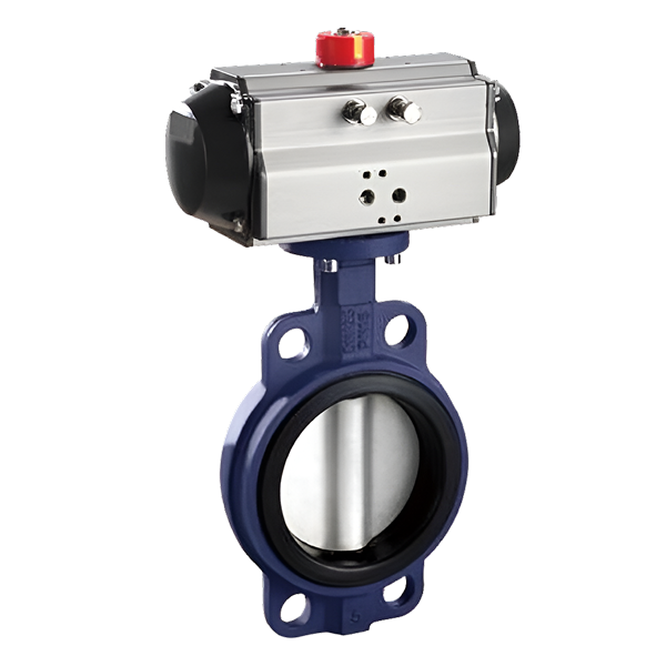
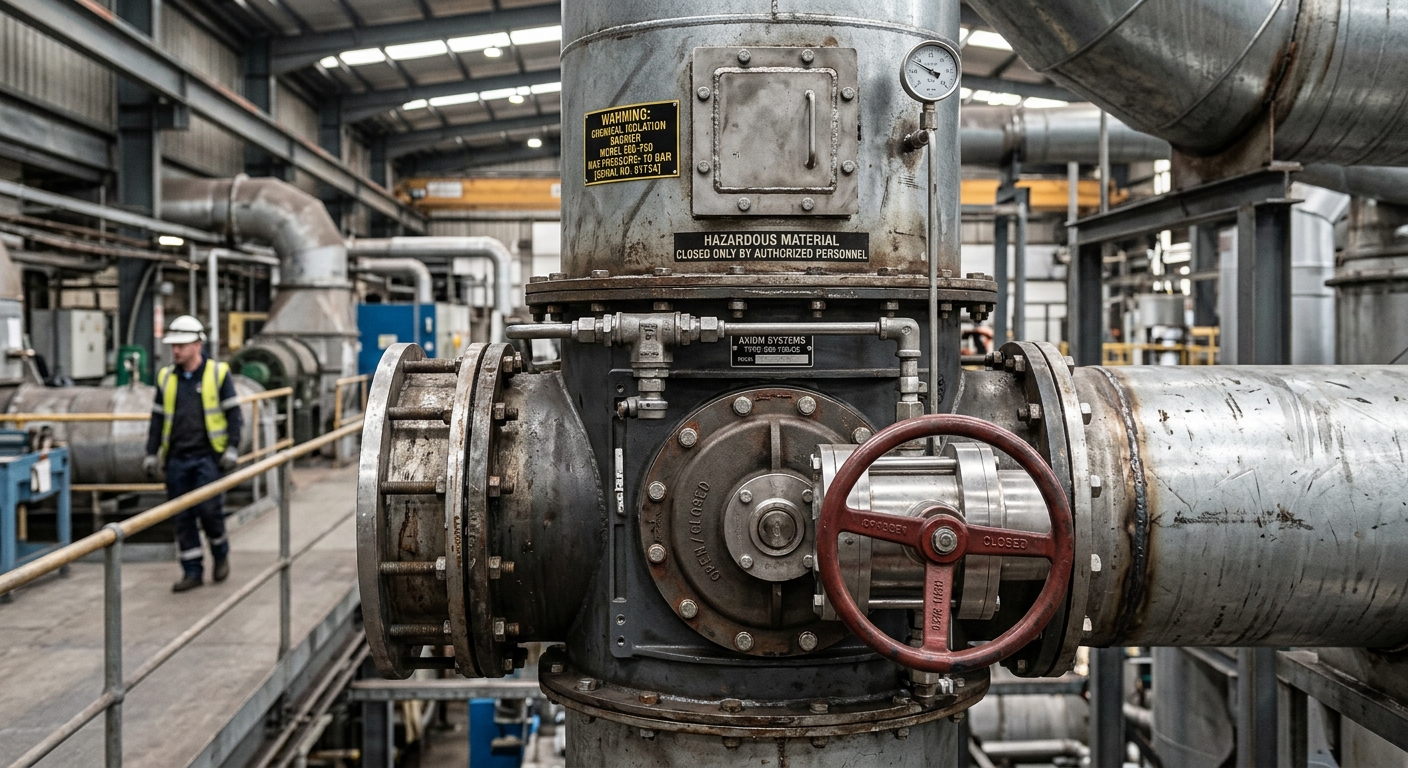
- Mechanical isolation: a fast-acting knife gate or float valve closes the duct within 30–50 ms. Passive float valves are elegant — the pressure wave itself slams them shut.
- Chemical isolation: an optical or pressure detector triggers a chemical barrier (typically sodium bicarbonate) injected across the duct cross-section, extinguishing the flame mid-flight.
If you're weighing the broader strategy question, our breakdown of explosion isolation vs explosion venting walks through the decision logic in more detail.
Suppression Systems: When You Can't Vent at All
Some silos sit inside multi-story buildings, near rail loading areas, or in retrofitted plants where venting routes simply don't exist. For these, active suppression is the answer.
A suppression system uses a pressure detector (response time under 2 ms) wired to high-rate-discharge bottles charged with sodium bicarbonate or monoammonium phosphate at 60 bar nitrogen. When the detector sees a pressure rise of 50 mbar in the first few milliseconds of an incipient explosion, the bottles fire suppressant into the silo through hemispherical nozzles. The flame is chemically extinguished before pressure exceeds 0.5 bar — well within the silo's structural limit.
The catch: suppression systems are expensive (often 3–5x venting), and they require rigorous quarterly testing of detectors, control panels, and bottle pressures. A common audit failure is finding nitrogen propellant pressure at 80% of spec — meaning the bottle would discharge late, after the explosion has already done its work.
Spark detection is closely related and often deployed upstream of the silo, at the conveyor or pneumatic transport stage. Our overview of the spark detection and extinguishing system covers how IR sensors catch a glowing ember before it ever reaches the silo headspace.
The Role of Dust Collection in Preventing Ignition in the First Place
Protection systems handle the worst-case scenario. But the cheapest explosion is the one that never starts. Properly designed dust collection at transfer points, weigh hoppers, and silo vents keeps airborne concentrations well below the lower explosive limit (LEL).
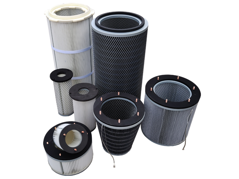
For grain dust the LEL is around 50 g/m³. Operating at less than 25% of LEL is the standard target. That requires capture velocity of 1–1.5 m/s at every transfer point and adequate filter media area sized for an air-to-cloth ratio of 1.5–2.0 m³/min per m² for pulse-jet cartridge collectors.
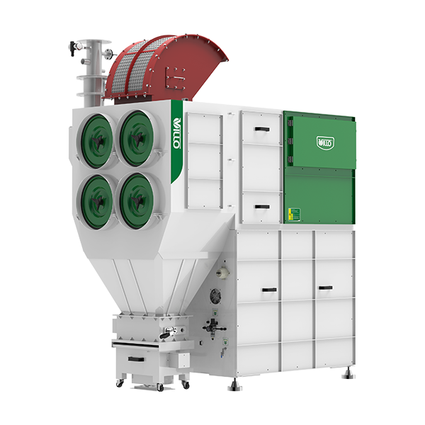
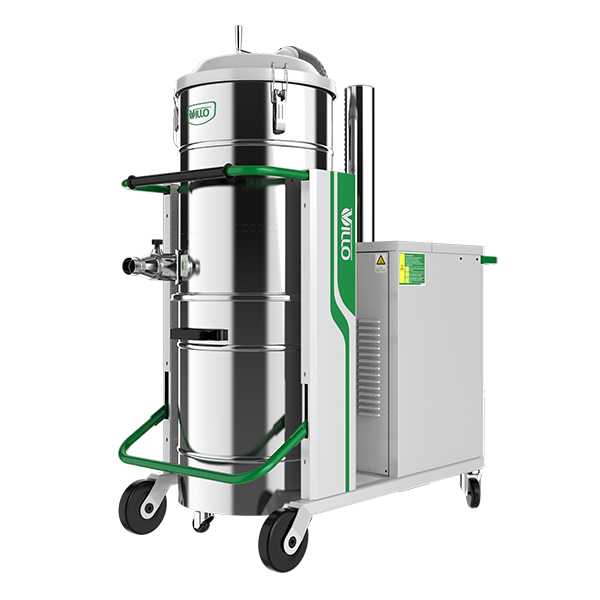
The collectors themselves need protection too — a dust collector handling grain dust is itself a primary explosion risk. ATEX-rated baghouses with their own venting, isolation valves on the inlet duct, and grounded antistatic filter bags are the baseline. The mechanics of how those filters keep cleaning themselves are explained in our walkthrough of pulse jet cleaning inside a dust collector.
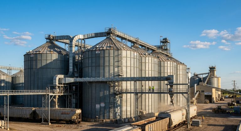
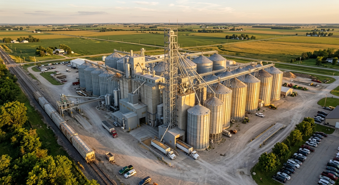
A Real-World Layout: How These Pieces Fit Together
Let's walk through a representative mid-sized feed mill with four 150 m³ outdoor receiving silos, a bucket elevator, and a central dust collector. Here's what a defensible protection layout looks like:
- Each silo: 4.5 m² vent panel on the roof discharging upward to a clear zone. Pressure detector tied to a control panel for incident logging.
- Bucket elevator: vent panels on the head and boot, plus a passive float valve on the discharge spout.
- Pneumatic transport line into silos: chemical isolation barriers within 8 m of each silo inlet.
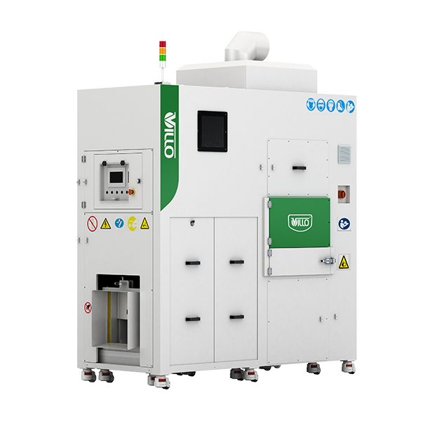
- Central dust collector: ATEX-certified, with explosion vent on the dirty side, flameless device option if located indoors, and a fast-acting knife gate on the inlet duct.
- Pre-silo conveyor: spark detection with water-mist extinguishing.
- Bonding and grounding: every silo, duct, and conveyor section verified at less than 10 ohms to earth.
For a deeper look at how these elements are integrated as one system rather than a pile of independent devices, see our reference design for a central dust collection and explosion protection system. Treating these as a single engineered package — rather than buying components piecemeal — is what separates compliant facilities from the ones that pass an audit but still aren't safe.
Maintenance: Where Good Systems Quietly Become Useless
Every protection system has an expiration date measured in inspection cycles, not years. A vent panel coated in three winters of bird droppings doesn't open at 0.1 bar anymore — it opens at 0.25 bar, which is well above what your silo can take.
Minimum maintenance schedule for a grain handling facility:
- Monthly: visual inspection of vent panels, isolation valves, and detector lenses.
- Quarterly: functional test of detector circuits, control panel batteries, and suppression bottle pressures.
- Annually: replace optical detector windows, recalibrate pressure sensors, verify grounding continuity, and replace any bag filters showing pinhole leaks.
- Every 5 years: replace explosion vent panels regardless of visual condition — fatigue from thermal cycling and minor pressure fluctuations changes burst characteristics.
A practical starting point is to widen your overall combustible-dust risk view first; our guide to dust explosion prevention causes and action is a useful reference when building or auditing a maintenance program.
Putting It Into Practice
Grain silo protection isn't one device, one standard, or one inspection. It's a layered system — prevention through capture and grounding, mitigation through venting and isolation, and last-line suppression where venting can't reach. Skip a layer and the math stops working.
If you're sizing a new silo, retrofitting an aging facility, or just trying to understand whether what you already have is genuinely protecting your people and your asset, villotech's engineering team can review your layout, run the venting calculations, and specify isolation and suppression hardware that matches your actual operating envelope rather than a generic template. Reach out through villotech.com when you're ready to dig into the specifics.